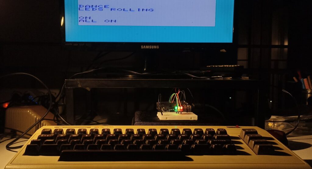
Today we can conveniently use a VIC-20 to control external devices via a custom built interface we can make with an inexpensive Arduino. Possibilities are endless, and we will step up from simple example to more and more interesting applications.
Arduino, VIC-20’s young friend
I am sure many readers of this blog know VIC-20 is equipped by two MOS 6522, I/O management chips making it suitable to read external switches, potentiometers (remember Commodore paddles?) and control external devices. In the VIC-20 Interfacing Blue Book we have seen plenty of easy electronics projects to perform tasks such as checking water level, controlling a telephone line, etc. But I bet the majority of readers didn’t dare to experiment in practice.
The problem is, risk of burning out a VIC-20’s chip due to a wrong wiring is there, and the VIC-20 itself has become a precious piece of hardware we want to protect. So here’s why I propose to use Arduino.
Arduino is a modern development board which is available today at a very cheap cost (say, starting from as low as 5$ for compatible models) and can perform the same device-controlling tasks. It has several digital I/O ports and analog ports, its circuits are well protected and it connects to any PC via USB. Its logic can be easily programmed via a free Integrated Development Environment (Arduino IDE). And surprise! Arduno natively communicates with a VIC-20 (and C64) on the serial port with no effort.
So, why would you risk your precious Commodore friend to turn on some lights when you can make it control a cheap Arduino that will do the dirty job under VIC’s command?
In this tutorial series we learn how to connect and pilot an Arduino via a VIC-20. Our purpose is to use VIC’s display and keyboard to control external devices via a custom built interface. In this first project we will focus on controlling colored leds, but in the next projects we’ll see more applications of increasing complexity using the same hardware. Possibilities are endless!
Tools and software presented in this 1st project should equally work also on Commodore C64.
Required hardware
A buying advice list is provided at the bottom of the page, just in case.
- Arduino Uno R3 (or other equivalent) and breadboard
- A physical VIC-20
- VIC-20 user port connector
- A 2-wire + GROUND cable. Tip: use a common audio cable.
- A few colored patch cables
- 3 colored leds (red, green, yellow)
- 3x 220 Ohm resistors
- (optional) 3.5mm audio stereo jack male + female
Which Arduino?
This tutorial should work on most Arduino boards, and even others that are compatible or similar. I used a cheap Arduino Uno R3 that comes in a prepackaged kit including USB cable, breadboard, leds, patches and several sensors, for as low as 10 Euros. For better safety, I also bought a plastic case for it whose price was around 1,50 Euro.
At the bottom of the tutorial you will find the links to what I bought.
Build the cable
 The first thing you need is to build the cable to connect VIC-20 and Arduino. The cable we are about to build will connect to the VIC-20’s user port at one side (serial port), and will plug into Arduino’s digital sockets at the other side.
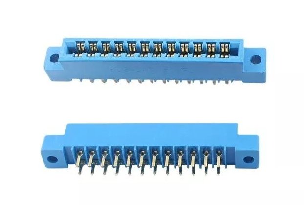
For this, you need to use a 24-pins user port connector.
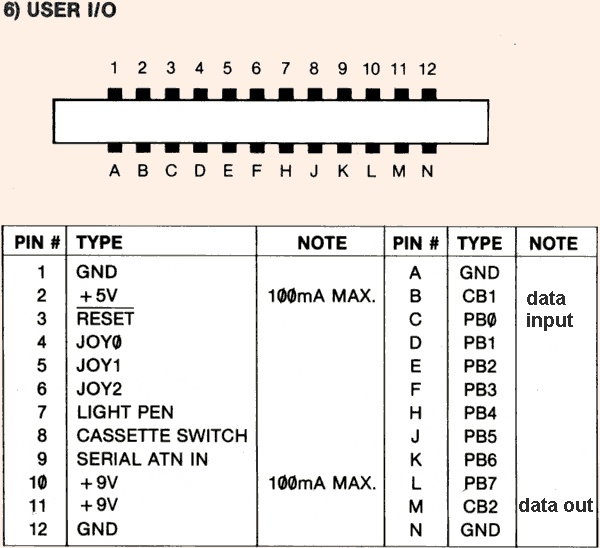 You need to wire TX, RX lines and Ground. You will find these pins in the bottom row, according to the diagram:
- RX = pins B+C together
- TX = pin M
- GND = pins A, N
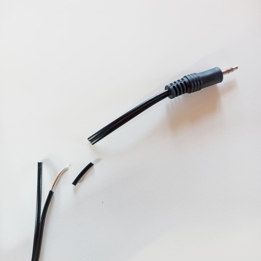
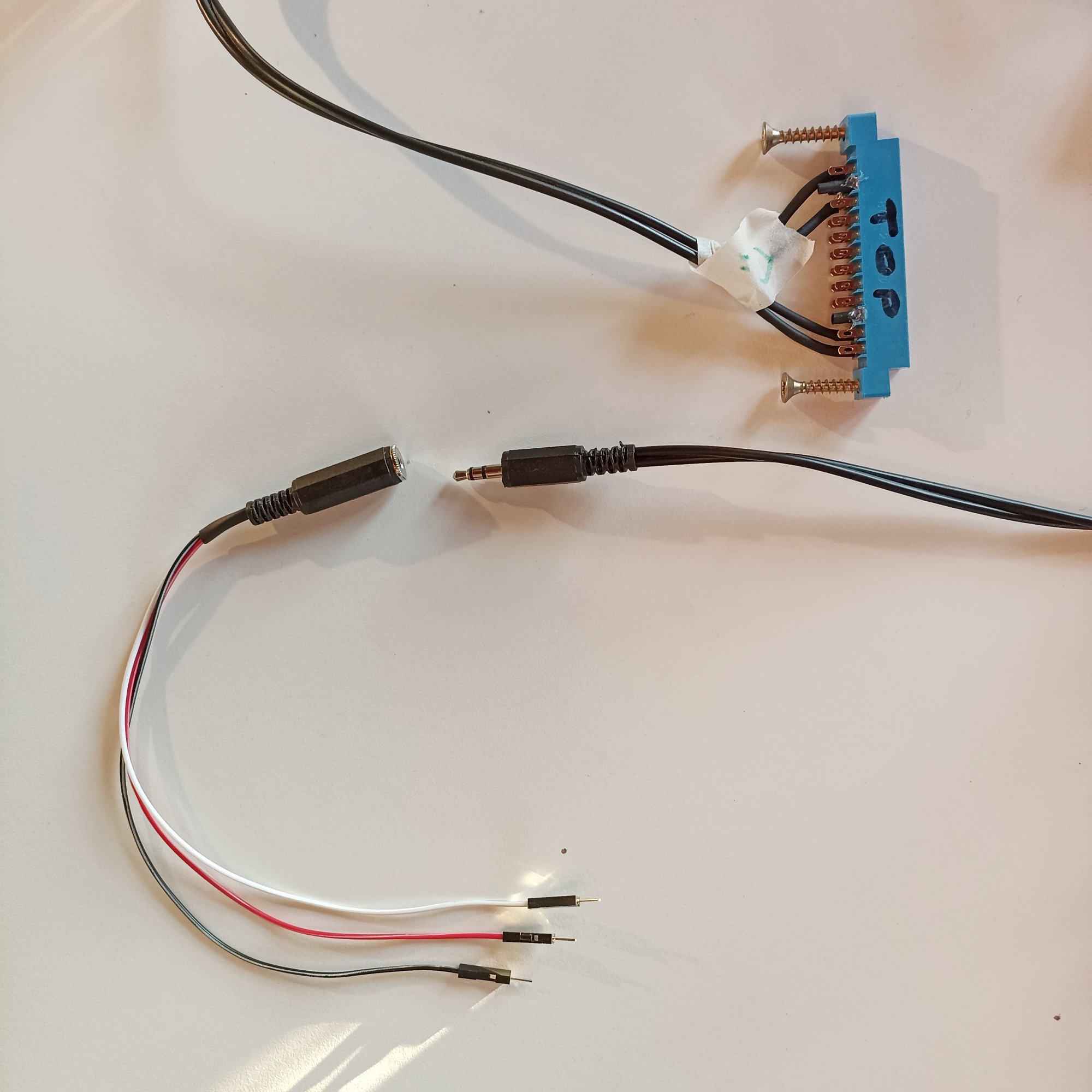
As a cable, I cannibalized an audio cable (Left, Right, Ground) as it was exactly what I needed. So I cut off the jack and peeled off the wires, then put a bit of soldering paste on the terminals.
 The idea is that VIC’s RX will go to Arduino TX socket, and Arduino’s RX to VIC’s TX.
On the Arduino you can choose which digital socket to use as RX/TX so once you have got the cable done at the VIC side, everything gets quite simple.
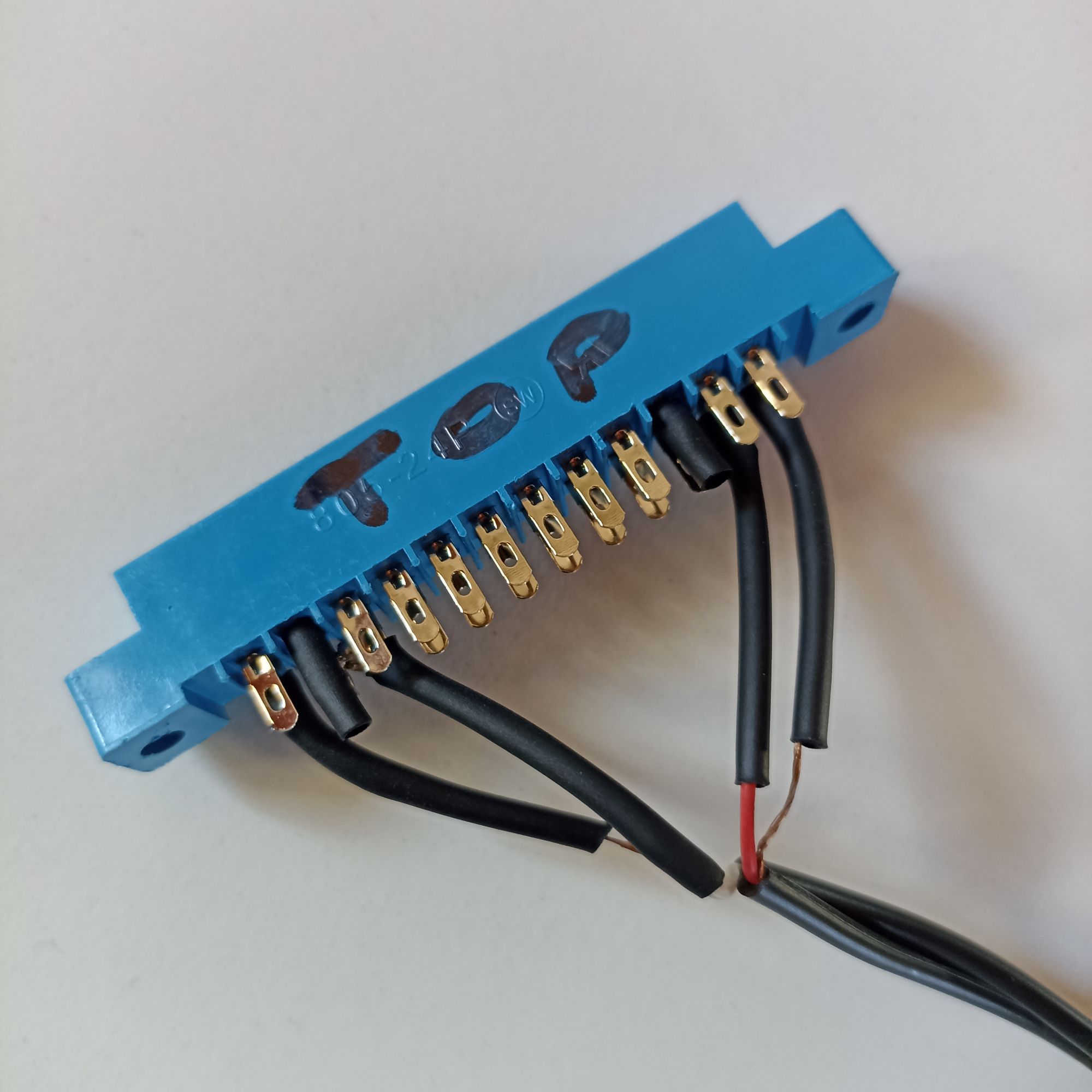
Remember to mark clearly one side of the user port connector with “TOP SIDE”, then put it upside down and start the soldering.
Below you can see the finished cable connector, top and bottom. In the second photo you see, white cable = VIC’s RX pin marked green and red cable = VIC’s TX pin marked pink.
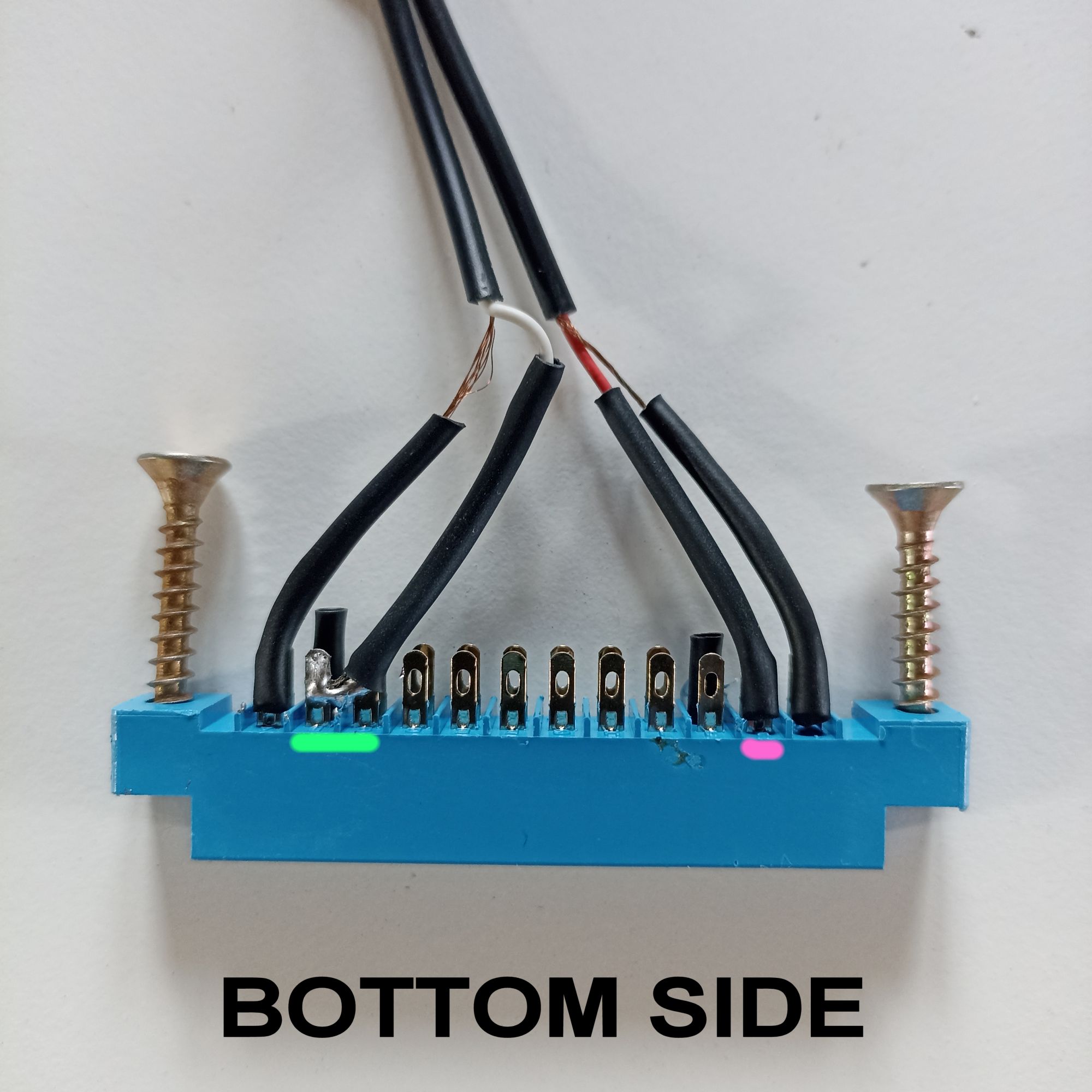
I tried to work as clean as I could despite my poor soldering skills. For increased security I recommend to add self-restringent plastic tubes around wires before soldering. I made them fit when finished soldering by using a hot air gun. I put this plastic tubes also around pins 2 and 10 just to avoid damages in case of wires touching them accidentally (I see just now that also pin 11 carries 9 volts, so I need to add this protection too). I finally glued the short protecting tubes in place with a tiny drop of hot glue (not shown in the pictures).
Before fitting into VIC-20 I recommend to insert two screws inside the connector’s side holes to help you pull it off conveniently later, unless you have also bought also the connector’s shell, I will show you a good option later.
Connections at Arduino’s side
I do not recommend to plug wires directly into Arduino’s sockets so, for first testing, on can use cables with crocodile clips like you see in the picture.
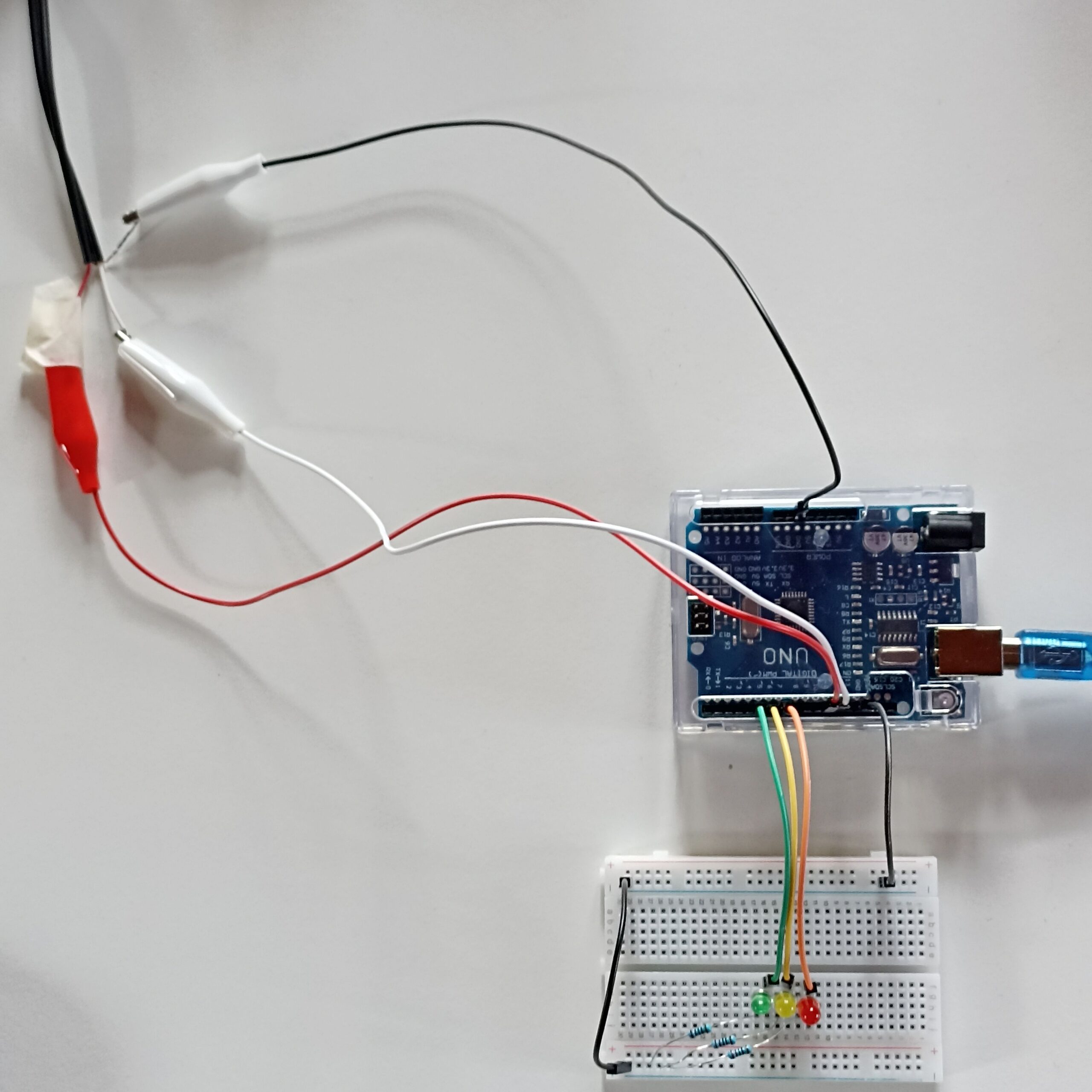
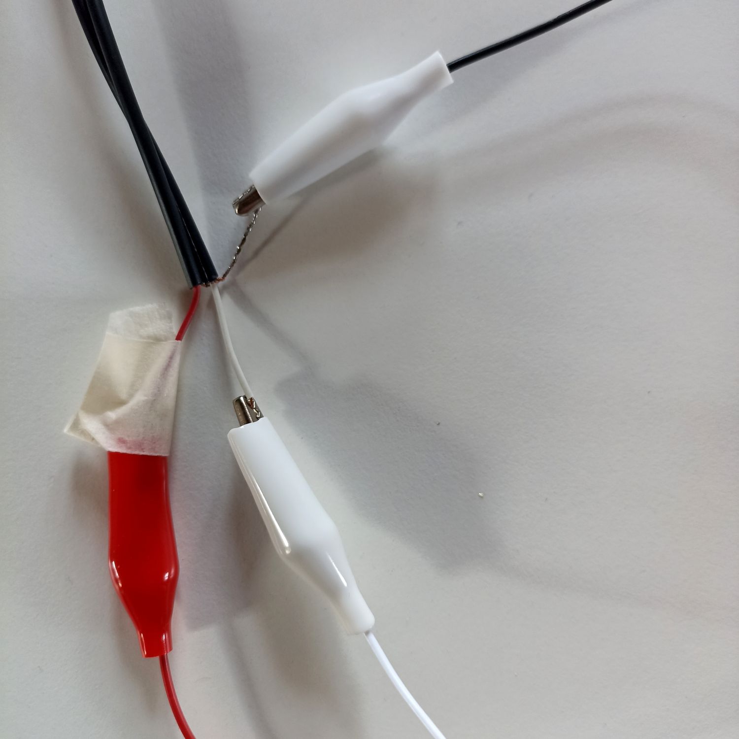
Here’s how to connect:
- VIC TX (red wire) goes to Arduino’s digital socket #11.
- VIC RX (white wire) goes to Arduino’s digital socket #12.
- GND should be connected to any Arduino GND socket.
Next and optionally, (it requires some extra soldering) you can replace this not-so-elegant connection with 3,5mm audio stereo jack male+female pair, as it makes everything much more cleaner and also it will allow to position Arduino+sensors many meters away from the VIC-20, by simply putting a long standard audio extension cable in-between.
Here is how the final part of the cable looks after the crocodile clips have been replaced by the audio jacks:
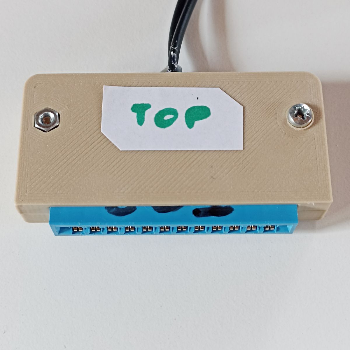
Finishing touch: the connector’s shell. Today it seems impossible to buy a cover the connector, but after some time I found a solution: an eBay seller produces 3D-printed shells at a convenient price so I got one. While you can find the link to the eBay item in the links at the bottom of the page, below you can see the final result:

Arduino controlled hardware
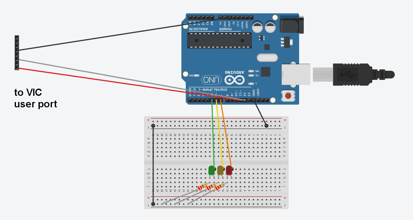
In this tutorial I just want to control three colored leds, so this part will be quite simple. In next tutorials this part will be replaced with different setup (ie. sensors, relais..). But let’s stick to our case now: three colored leds I used were coming from the original Arduino kit.
(In case you don’t know yet: Arduino’s breadboard has internally connections you should be aware of. Each central section of the breadboard has holes which are vertically interconnected with respect to the following picture. Along the top and bottom borders, instead, holes are horizontally interconnected, so holes on “+” and “-” lines are interconnected). We use one of the two to carry GND signal around.
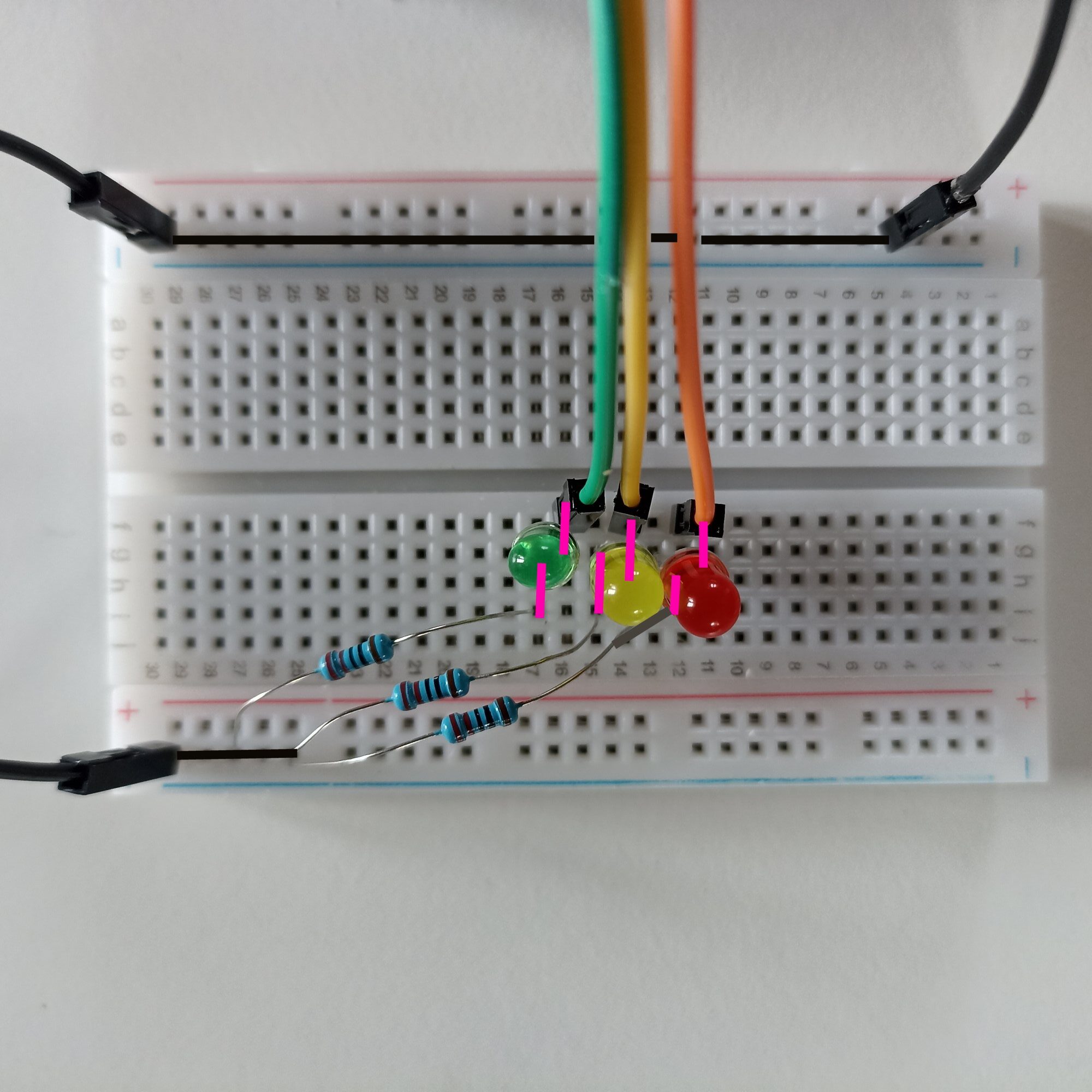
 Using the Arduino breadboard, fit the three colored leds side by side in one of the breadboard central section. Let’s say that Cathode (=negative pin, short leg) will be always inserted at left, while the Anode (=positive pin, long leg) will be inserted in the next hole, standing on the right side of the led)
- Under each led’s left leg we insert a 220 ohm resistor (also coming from the basic Arduino kit) and the other resistor’s leg is plugged in the “-” line at the side of the breadoard.
- Over each led’s right leg we insert a patch cable. I plugged each patch (see the are colored as leds) into digital sockets 5,6,7.
- Finally, border “-” lines are connected together by a black patch cable, and another black patch cable goes to the GND socket of the Arduino box.
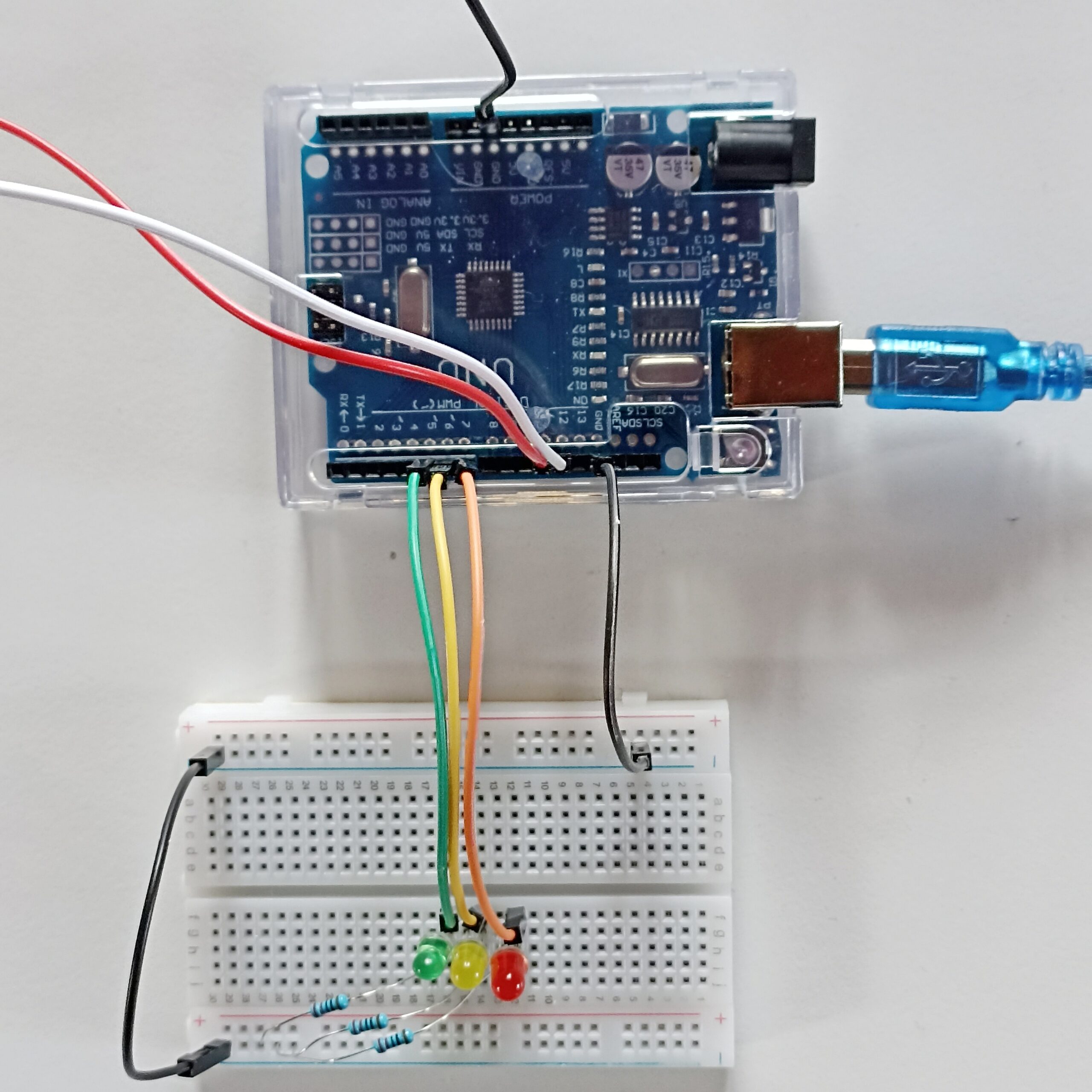
If you want to see visually what the connections in the breadboard really are now, here it is:
I also tried to make a cleaner diagram by using Tinkercad, hope it helps:
Software
VIC-20 side
Here is the simple terminal program:
10 OPEN2,2,0,CHR$(8)+CHR$(0)
20 GET#2,A$:PRINTA$;
30 GETA$:PRINTA$;:IFA$<>""THENS$=S$+A$
40 IFA$=CHR$(13)THENPRINT#2,S$;:S$=""
50 GOTO20
It opens a serial connection at 1200 baud, prints what it receives, and sends to Arduino what you typed.
You can type it via keyboard directly or, if you’ve got my vic20-network.d64 diskette, you already have this program, it is named TERM1200
Arduino side
You can download the sketch (.ino project) as a ZIP file here. Just unpack in your Arduino projects folder and you’re ready to open it. Below you can see the code. But please do not copy from here, download the sketch file instead, it’s more accurate.
// Arduino Software Serial library // Allows our Arduino Uno to communicate both with PC (local) and VIC-20 #include#define WHITECABLE 12 // VIC RX #define REDCABLE 11 // VIC TX int redled=7; int yellowled=6; int greenled=5; bool serialprinted; // Are we done printing on serial? bool vicprinted; // Are we done sending to VIC? char buf[255]; // String buffer -coming from VIC20 bool leds[8]; // Remembers which leds are on // Set up our Software Serial SoftwareSerial VICSerial(REDCABLE,WHITECABLE); // Initialisation stuff - runs once on power-up/reset void setup() { // put your setup code here, to run once: // Open serial communication and wait for port to open: Serial.begin(1200); while (!Serial) { ; // Wait for serial - Only needed for built-in USB } // Send out local startup message Serial.println("ATTEMPTING TO CONNECT TO VIC-20 ..."); // Set the baud rate to speak to VIC VICSerial.begin(1200); // Send message to VIC VICSerial.println("HELLO VIC-20?"); //Programs sockets for leds pinMode(redled,OUTPUT); pinMode(yellowled,OUTPUT); pinMode(greenled,OUTPUT); // Leds all OFF digitalWrite(redled,LOW);leds[redled]=false; digitalWrite(yellowled,LOW);leds[yellowled]=false; digitalWrite(greenled,LOW);leds[greenled]=false; // Clear utility vars memset(buf,0,sizeof(buf)); // Clear buffer. serialprinted=false; vicprinted=false; } void loop() { char rx; // put your main code here, to run repeatedly: // IF THE VIC20 HAS DATA THEN PRINT IT HERE if (VICSerial.available()) { rx=VICSerial.read(); if (strlen(buf)<200) { if (rx>47) { // Character buf[strlen(buf)]=rx; } else { // Should be CR serialprinted=true; } } } else { if (serialprinted) { serialprinted=false; Serial.println(); Serial.println(buf); //dumpStr(buf); if (strcmp(buf,"R")==0) { Serial.println("Choice: R for RED"); ledsToggle(redled); } else if (strcmp(buf,"G")==0) { Serial.println("Choice: G for GREEN"); ledsToggle(greenled); } else if (strcmp(buf,"Y")==0) { Serial.println("Choice: Y for YELLOW"); ledsToggle(yellowled); } else if (strcmp(buf,"OFF")==0) { VICSerial.println("ALL OFF"); ledsOff(); } else if (strcmp(buf,"ON")==0) { VICSerial.println("ALL ON"); digitalWrite(redled,HIGH);leds[redled]=true; digitalWrite(yellowled,HIGH);leds[yellowled]=true; digitalWrite(greenled,HIGH);leds[greenled]=true; } else if (strcmp(buf,"DANCE")==0) { VICSerial.println("LEDS ROLLING"); ledsDance(); } else { //Serial.println("No command for this string"); } memset(buf,0,sizeof(buf)); // Clear buffer. } } // PASS ANY CHARS RECEIVED FROM PC *TO* VIC .. if (Serial.available()) { VICSerial.write(Serial.read()); vicprinted=true; } else { if (vicprinted) VICSerial.println('\n'); vicprinted=false; } } //******************** My Routines ****************** void ledsToggle(int line) { if (leds[line]) { digitalWrite(line,LOW); leds[line]=false; } else { digitalWrite(line,HIGH); leds[line]=true; } } void ledsOff() { digitalWrite(redled,LOW);leds[redled]=false; digitalWrite(yellowled,LOW);leds[yellowled]=false; digitalWrite(greenled,LOW);leds[greenled]=false; } void ledsDance() { int j,i; for (j=0;j<3;j++) { for (i=greenled;i<=7;i++) { digitalWrite(redled,LOW);leds[redled]=false; digitalWrite(yellowled,LOW);leds[yellowled]=false; digitalWrite(greenled,LOW);leds[greenled]=false; ledsToggle(i); delay(1000); } } ledsOff(); } // DO NOT copy the following line!
Here we will not cover the basics of Arduino IDE and language. Anyway, the Arduino IDE can be downloaded and used at no cost from its official website.
- After loading the project in Arduino IDE, please connect Arduino to PC via its USB cable.
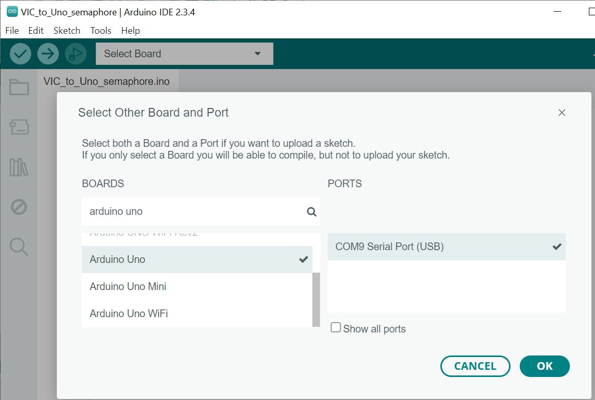
 from the “Select Board” dropdown, search in the list the Arduino board type you are using (I was using “Arduino Uno”) and select the virtual COM port it appears to be using.
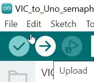
- Finally hit the Arrow/Upload button to compile the code and upload it to Arduino.
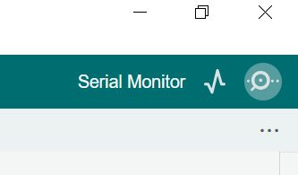
Make sure to open the Serial monitor (button top right) and set its speed at 1200 baud from the onscreen dropdown. That’s it!
Have fun!
- Type on VIC-20 keyboard to pilot lights. Press RETURN to send command to Arduino.
- R turns Red led On/off
- Y turns Yellow led On/Off
- G turns Green led On/Off
- ON will turn all leds on
- OFF will turn all leds off
- DANCE will produce a simple sequence 3 times, then turn leds off
- Every other string you type will be sent to Arduino after pressing RETURN. You will see that string echoed in the Arduino IDE’s serial monitor on PC, if connected.
- If you type in the serial monitor on your PC, typed strings will be transmitted and visualised on VIC-20.
There is a small video I made for this test you can watch on youtube.
This tutorial is over! Hope you liked it, please let me know in the comments, and stay tuned for thext part!
Where I bought hardware
These are from where I bought but, other dealers will be fine too.
- User Port connector – ebay (suggestion: search for “c64 user port” when searching, the ports are identical in the two systems)
- Arduino Uno R3 kit: from Temu
- Transparent box for Arduino Uno: from Temu
- Cover shell for the user port edge connector: from eBay
Credits
The base stuff for this tutorial came from this one, whose author I thank very much. Of course these techniques will work on c64s too!
