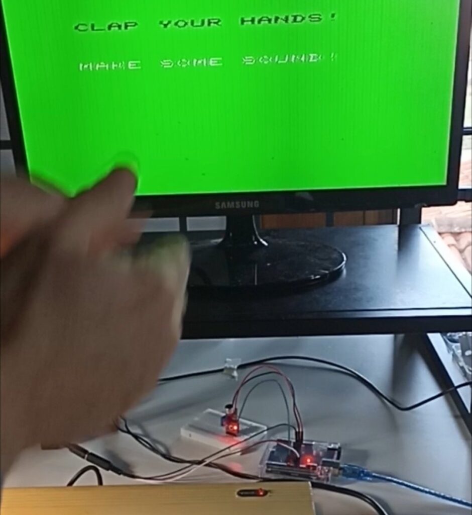
In this 3rd tutorial we will make the VIC-20 react to sound. One finger snap to change screen’s background color, two claps will change background and border.
As in previous projects of this series, Arduino is just a sensor used by VIC-20. It senses sounds, counts the number of hand claps, then sends the number of sensed sounds to VIC-20 over the serial line by using the cable we built in project 1.
Required hardware
- Arduino Uno R3 (or other equivalent) and breadboard
- KY-037 Sound sensor (buying advice at the bottom)
- A few patch cables
- A physical VIC-20
- VIC-20 user port serial cable (as built in project #1)
Building it
Here is a schematic diagram:
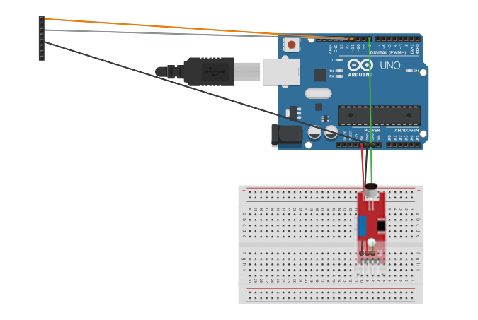
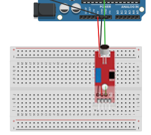
- Plug the sensor in the breadboard so that the four pins A0,G,+,D0 occupy the most external row of lines 10,9,8,7 (A0 goes into line 10, G in line 9, etc).
- Black patch cable from Arduino power block GND to breadboard (say, line 9)
- Red patch cable from Arduino power block 5V to breadboard (say, line 8)
- Green patch cable from Arduino digital pin #8 to breadboard (say, line 7)
If everything is like I explained, sensor’s pin A0 should be fitted in breadboard line 10, unconnected. We will not use the analogue function of the sensor.
I chose this way of placing the sensor with face outwards because it will be easier for you to calibrate it later.
The remaining connections (cable to VIC-20) stay the same as in the previous projects so:
- White serial line: digital pin #12
- Red serial line: digital pin #11
- Ground of serial line: Arduino power block GND
After building it, connect Arduino to your PC and proceed with sensor calibration.
KY-037 Sensor Calibration
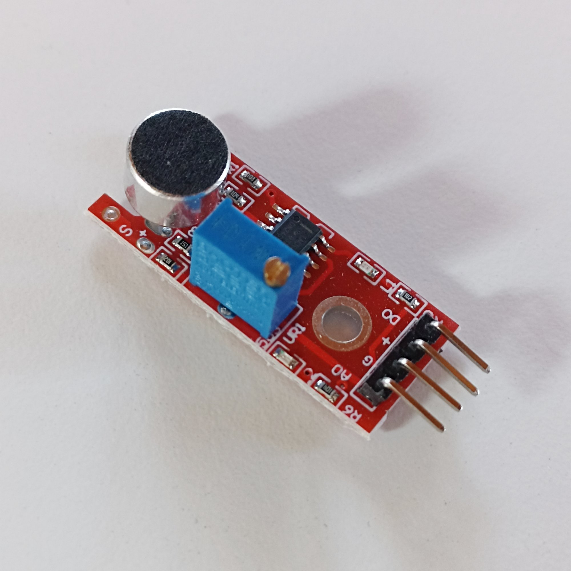 KY-037 sound sensor is a very useful and inexpensive sound sensor. I found it included in my basic Arduino Uno R3 package. If you haven’t got it yet, you will be able to buy one for very little money. Here I will cover also the task of calibrating it, as I found almost NO instructions to do so on the net, even the manufacturer doesn’t tell you how to do it.
I even ended up buying more sensors because I thought the one I alredy had was faulty and, guess what, it was perfectly working. Simply put, nobody tells you how to calibrate it.
So, in order to calibrate the sensor, place yourself in a quiet place, get a tiny screwdriver and connect the circuit with Arduino to your PC or to a power supply.
Now, the sensor has two leds: one (right side, when watching the blue box) should always be lit up, it means the sensor is powered and working.
The second led (left side, below the blue box) lits up only when the detected sound is higher than a threshold set by the potentiometer (the little blue box with the screw).
Therefore in a normal condition of silence, only one led should be lit up. You have a 99.99 chance that you see both leds lit up: if so, the sensor needs calibration.
After keeping the sensor in place with a finger, carefully unscrew the little screw on top of the blue box, by turning counter-clockwise. Again. Again. Again. Unscrew MANY MANY times! Go ahead and trust me, unscrew until you see that one of the leds turns off.
Finally, try clapping hands. If you see the led (left side) reacts correctly to the sound, yu have calibrated it. If it does not lit up, you have unscrewd too much, turn clockwise a little until you find the correct position.
We will not use the sensor’s analogue function. We will use its digital output (D0) which will be 1 when a sound is detected (led on) and 0 when there is silence (led off).
Arduino software
Load the project software (sketch file) inside the Arduino IDE. The sketch file can be found inside the ZIP you download by clicking below:
Software package: VIC-20 and Arduino – project 3
Just unzip it, you will find three things:
- the .ino sketch (actually a folder named “VIC_to_Arduino_p3_Sound_sensor” with a .ino file inside)
- the VIC-20 program to use Arduino+the sensor named soundsens-p3.prg
Move the folder “VIC_to_Arduino_p3_Sound_sensor” into your Arduino projects folder. Then start Arduino IDE and open the sketch “VIC_to_Arduino_p3_Sound_sensor.ino” file.
Below the listing of the software, let’s comment it out a little bit.
// VIC-20 to Arduino - project 3: Sound Sensor // Arduino Software Serial library // Allows our Arduino Uno to communicate both with PC (local) and VIC-20 #include#define WHITECABLE 12 // VIC RX #define REDCABLE 11 // VIC TX int sensorPin = 8; // Set up our Software Serial SoftwareSerial VICSerial(REDCABLE,WHITECABLE); // Initialisation stuff - runs once on power-up/reset void setup() { // put your setup code here, to run once: pinMode(sensorPin,INPUT); // prepare Sound sensor pin for reading // Open serial communication (PC) Serial.begin(1200); while (!Serial) { ; // Wait for serial - Only needed for built-in USB } // Send out local startup message Serial.println("ATTEMPTING TO CONNECT TO VIC-20"); // Set the baud rate to speak to VIC VICSerial.begin(1200); // Send message to VIC VICSerial.println("START"); } void loop() { unsigned int i,j; int sound_detected; // How many sounds have been detected? sound_detected=0; for (i=0;i<63000;i++) { for (j=0;j<3;j++) { if (1==digitalRead(sensorPin)) { sound_detected++; Serial.println("SOUND!"); delay(40); } if (sound_detected>2) { // Double clap - Quick exit i=63000; j=1000; } } } if (sound_detected>0) { Serial.print("Sending: "); Serial.println(sound_detected); VICSerial.println(sound_detected); // Send number of detected sounds to VIC sound_detected=0; delay(60); } Serial.print("."); } // If you copy+paste, DO NOT copy anything below this line
As for previous projects, remember to select Arduino model and serial port from the board selector dropdown before uploading the code.
In this project, Arduino does not get commands from VIC-20. The provided code reads the sound sensor and seeks to count how many sounds (claps, finger snaps) it gets in a time span of about one second.
Then, it sends the number of sounds it got (1 or more) to VIC-20 which will parse the received string, convert it into a number, then il will react depending if we got 1 clap or more sounds.
As for previous projects, we can see what Arduino sends to VIC inside the Serial debug window in the Arduino IDE (remember to set it to 1200 baud speed).
VIC-20 Software
The program is included in the software package you have downloaded from this page, it is in PRG format and you should transfer it onto a diskette or a SD2IEC device. If you don’t have them, you can type it directly.
The program should run also on the unexpanded because it’s very short. Anyway I developed with the +8K expansion so please always load it with a simple LOAD (without the final ,1) in order to allow relocation if using the unexpanded VIC.
Owners of C64 might want to adapt/write something appropriate for their system – the hardware will work for both systems!
2 print"{clear}{black}{down*5}{right*2}clap your hands!"
4 print"{white}{down*4}{right*2}make some sound!"
5 open2,2,0,chr$(8)+chr$(0):sc=36879
10 rem *********
11 rem main loop
12 rem *********
20 get#2,a$:ifa$=""then20
30 ifa$=chr$(10)then20
32 ifa$<>chr$(13)thenb$=b$+a$:goto20
35 remprint"(";b$;"){space*2}";
40 ifb$<>""thenv=val(b$)
42 remprint"-";v
45 ifv=1thengosub3000:b$="":goto20
46 gosub2000:b$="":goto20
50 goto20
2000 rem ***********
2001 rem change colr
2002 rem ***********
2008 c=c+1:n=c-int(c/8)*8
2010 on(n+1)goto2021,2022,2023,2024,2025,2026,2027,2028
2015 stop
2021 pokesc,8:return
2022 pokesc,25:return
2023 pokesc,42:return
2024 pokesc,59:return
2025 pokesc,76:return
2026 pokesc,93:return
2027 pokesc,110:return
2028 pokesc,127:return
3000 rem ***********
3001 rem change bordr
3002 rem ***********
3008 b=b+1:ifb>15thenb=0
3010 ifb=nthen3008
3012 poke36879,((peek(36879)and7)or8)orb*16
3020 return
Lines 2-5: Open the serial connection with Arduino
Lines 10-50: Main loop: read chars from serial input, build into a buffer string B$, which gets converted into an integer value V when a carrage return CHR$(13) is encountered. If V=1 single sound – go to subroutine 3000. If more sounds, g to subrountine 2000
Line 2000 (subroutine): Change border+background color. A double clap must have been detected so we set a new color combination on screen (we want border color equal to background color, there are 8 combinations possible on the VIC-20). The formula
N=C-INT(C/8)*8
equals to the pseudo code: N = C MOD 8 (CBM BASIC does not have the MOD operator!). So N is the remainder of the division C/8, a number from zero to 7. We do this in order to cycle between numbers 1…8 when incrementing N.
The ON N GOTO … construct jumps us to the desired POKE combination to get the screen colored for each specific combination.
Line 3000 (subroutine): Change background color. We use this one to cycle background color to the 16 possible colors. Instead of using the MOD formula as in the previous subroutine, I preferred here to use a simpler approach: when the background color code B gets to 16, we reset it to zero.
The instruction
POKE 36879,((PEEK(36879) AND 7) OR 8) OR B*16
is interesting. It allows to change the background color by putting our wanted color code (kept in the B variable) inside the appropriate bits (4 to 7) in the 36879 memory location (=VIC register) while keeping border color intact.
bits 0-2 control border color, that’s why we “AND 7”: we want to keep all those bits as they are.
In the same register, “OR 8” will set bit 3 ON: that one bit controls normal or reverse mode and it must be set to ON.
Finally “OR B*16” has the effect of writing the color code kept into B starting by bit #4: in fact 16 (to which we multiply B) is 2 ^ 4.
Keep the above instruction for future needs, it might come handy to change background color without need of the color tables.
As it stands, in this project VIC-20 does not send any command to Arduino.
Conclusions
We have seen how to use Arduino as an interface to control a sound sensor. VIC-20 receives information and reacts to single and repeated (or long) sounds.
Here is a small video I made for showing it up:
Buying advice
If you don’t know where to get the parts for this project:
- Arduino Uno R3 kit – from Temu – it includes the KY-037 sensor already.
- The KY-037 sensor (2x minimum), from Temu
If you liked this tutorial, stay tuned! More interesting stuff coming up next (SUBSCRIBE for free to email notifications!)
