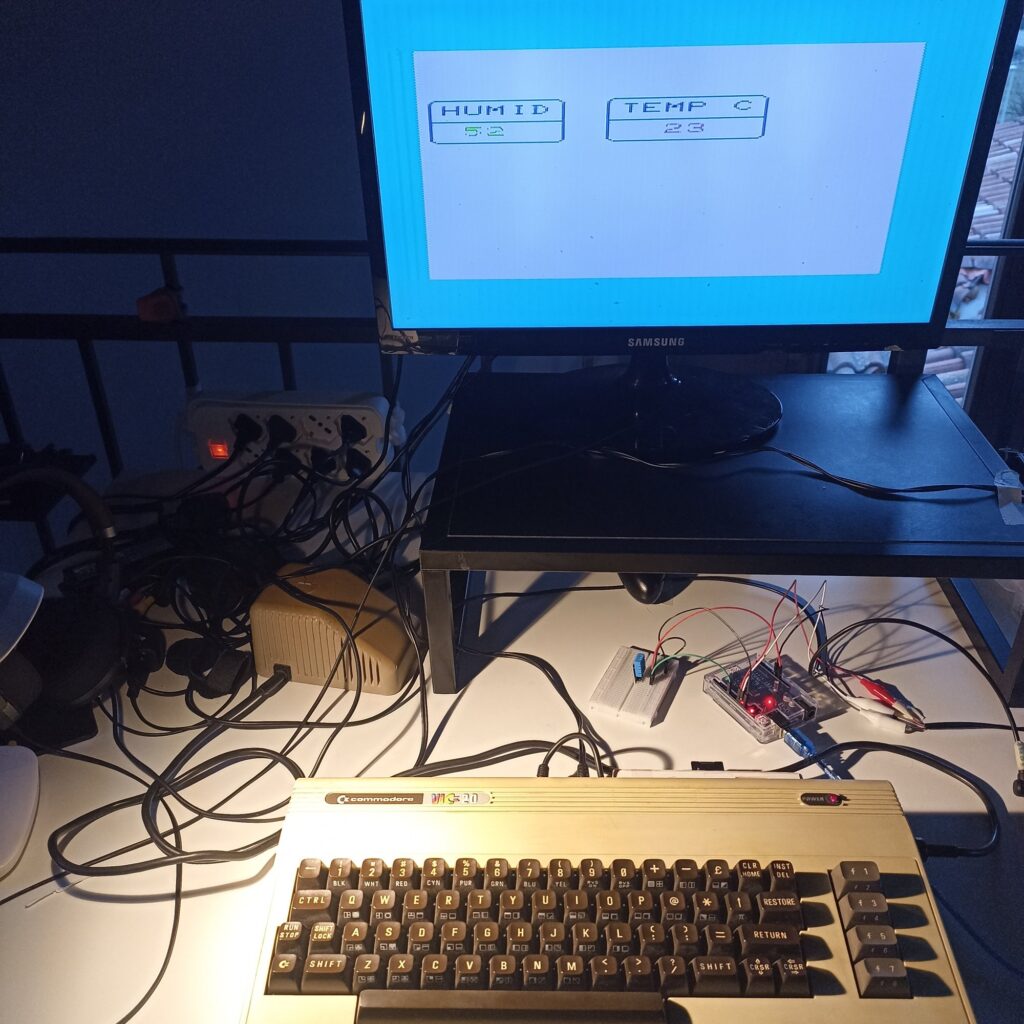
In this second tutorial we will use the cable we built in tutorial 1 to create a sensor of temperature and humidity displaying data on the VIC-20 screen
As it should be clear, here Arduino does only the dirty job of interfacing VIC-20 with a modern and cheap humidity and sensor.
Everything will be controlled by VIC-20 (sensing frequency) and the display of data will be performed using the VIC-20 screen.
Come and follow me in this series of tutorials, as our VIC-20 will be soon capable of incredible things!
Required Hardware
- Arduino Uno R3 (or other equivalent) and breadboard
- DHT11 Temperature & Humidity sensor (buying advice at the bottom)
- A few patch cables
- A physical VIC-20
- VIC-20 user port serial cable (as built in project #1)
 Some words on this DHT11 sensor. It was included in my basic Arduino Uno R3 package, and I found it convenient, reliable and simple to use. Furthermore, if you don’t have it you can buy it for as little as 1,50 USD from online stores. Finally, you will need to load its specific library to work inside Arduino IDE: this covered by this tutorial. I will include the software library I used inside the tutorial’s software package for your convienience, but please, should you purchase this sensor, always look for the updated library from your vendor just to stay on the safest side.
Building it
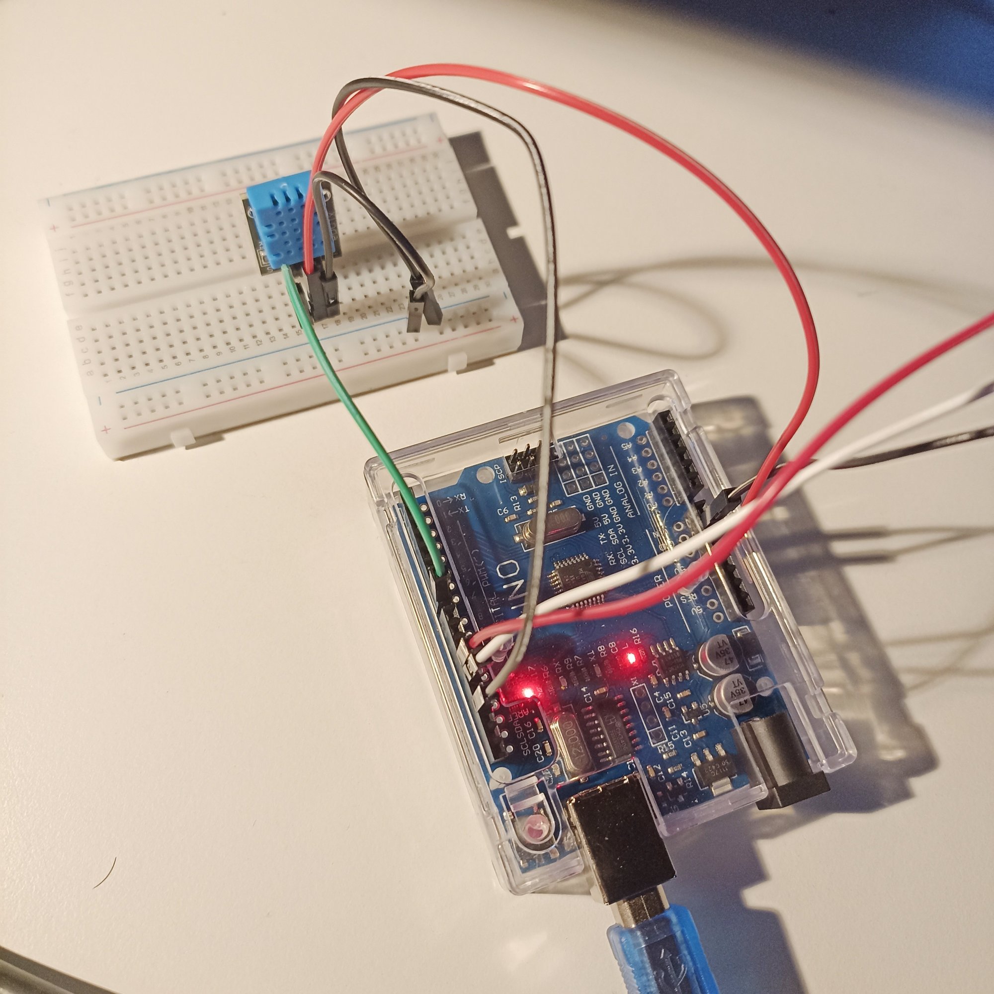
- From the serial cable the connections remain as in project 1, that is: VIC TX/red –> #11 VIC RX/white –> #12, ground to ground (power pins block)
- +5V (power block): connect to breadboard as indicated with a (red patch)
- GND (digital pins block): connect to breadboard as indicated (black patch). You can also avoid using two patches like I did and go directly to the target sensor pin line with just one patch. Here, I used two patches in order to make a GND line along the border, just to be more comfy in case I want to add up things later.
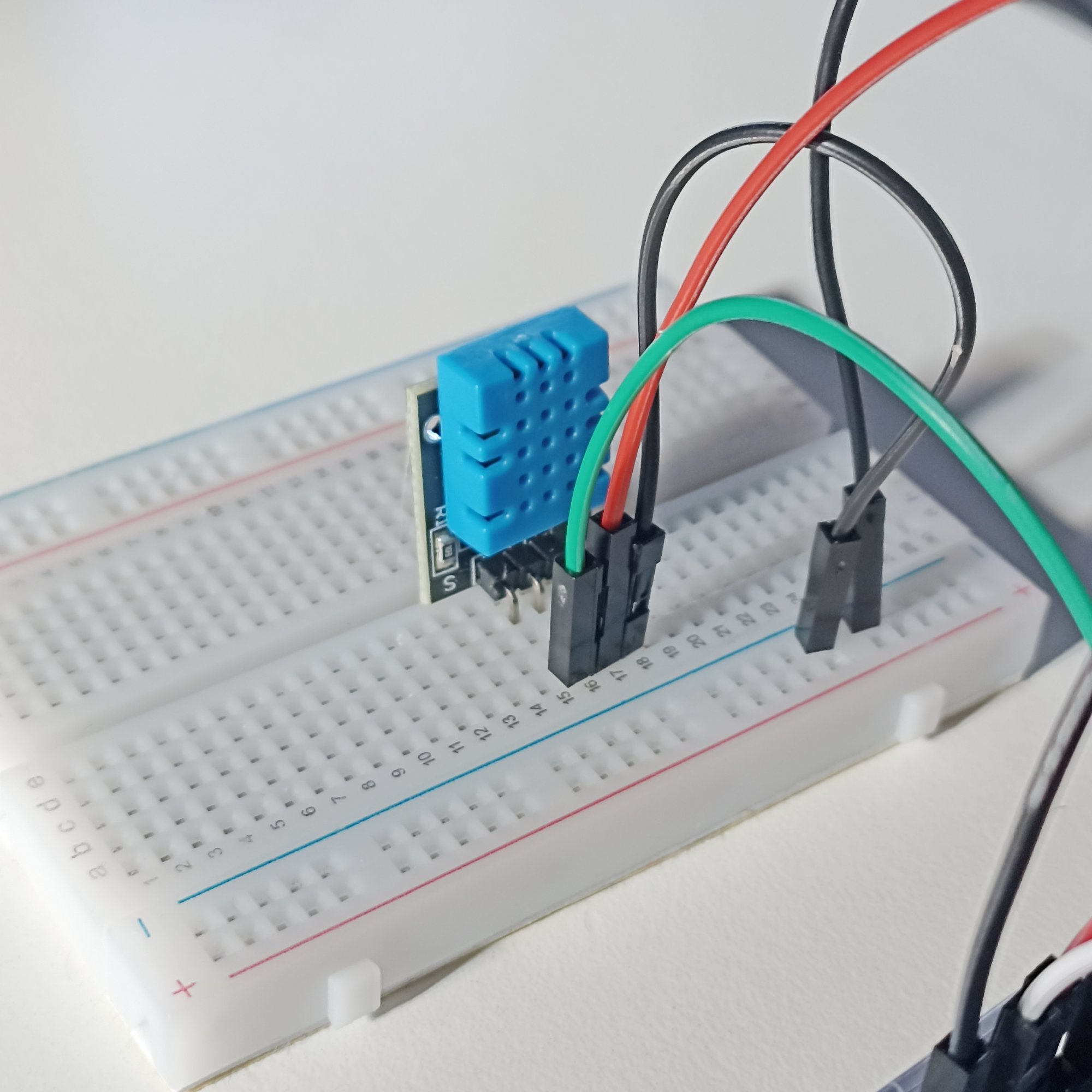
- Digital pin #8: connect to breadboard as indicated (green patch)
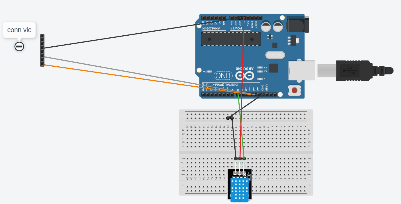
Finally, plug the sensor on the breadboard as indicated. Check on the sensor card that “S” matches the colored line, and that GND matches the GND line.
Connect Arduino to your PC and proceed with the next step: loading the sketch file (Arduino software) into the Arduino IDE.
Arduino software
The sketch file can be found in the global ZIP you can download clicking below:
Software package for VIC to Arduino project 2
Just unzip it, you will find three things:
- the .ino sketch (actually a folder named “VIC_to_Arduino_p2_Humidity_Temp” with a .ino file inside)
- a copy of the sensor library: Dht11.ZIP file
- the VIC-20 program to pilot Arduino+the sensor named humidtemp.prg
Move the folder “VIC_to_Arduino_p2_Humidity_Temp” into your Arduino projects folder. Then start Arduino IDE and open the sketch “VIC_to_Arduino_p2_Humidity_Temp.ino” file.
Install the sensor library
If you’re familiar with Arduino IDE, you already know how it works.
From the menu choose Sketch –> Include Library –> Add .ZIP library…
the browse to the folder where your DHT11 library resides. If you followed my advice at the top, you will be using your vendor’s provided library. If your vendor did not provide one, then I hope my copy will be OK for your sensor (if yours is like mine, it should work).
This step will make this directive:
#include < dht11.h >
to work without errors.
Arduino code
Let’s say something on the Arduino code for this project:
// Arduino Software Serial library // Allows our Arduino Uno to communicate both with PC (local) and VIC-20 #include// DHT Temp humidity sensor #include #define WHITECABLE 12 // VIC RX #define REDCABLE 11 // VIC TX bool vic_command_received; // Are we done printing on serial? bool vicprinted; // Are we done sending to VIC? char buf[255]; // String buffer -coming from VIC20 char outbuf[255]; // String buffer - output to VIC20 dht11 DHT; #define DHT11_PIN 8 // Set up our Software Serial SoftwareSerial VICSerial(REDCABLE,WHITECABLE); // Initialisation stuff - runs once on power-up/reset void setup() { pinMode(DHT11_PIN, OUTPUT); // put your setup code here, to run once: // Open serial communication and wait for port to open: Serial.begin(1200); while (!Serial) { ; // Wait for serial - Only needed for built-in USB } // Send out local startup message Serial.println("ATTEMPTING TO CONNECT TO VIC-20 ..."); // Set the baud rate to speak to VIC VICSerial.begin(1200); // Send message to VIC VICSerial.println("HELLO VIC-20?"); // Clear utility vars memset(buf,0,sizeof(buf)); // Clear buffer. vic_command_received=false; // Becomes TRUE when a complete command is received from VIC vicprinted=false; // Have I sent chars from PC to VIC? } void loop() { char rx; memset(outbuf,0,sizeof(outbuf)); // Clear buffer. // put your main code here, to run repeatedly: // IF THE VIC20 HAS DATA THEN PRINT IT HERE if (VICSerial.available()) { rx=VICSerial.read(); if (strlen(buf)<200) { if (rx>47) { // Character buf[strlen(buf)]=rx; } else { // Should be CR vic_command_received=true; } } } if (vic_command_received) { Serial.print("RECEIVED:"); Serial.println(buf); //dumpStr(buf); if (strcmp(buf,"CK")==0) { Serial.println("CHECKING"); memset(outbuf,0,sizeof(outbuf)); // Clear buffer. /* outbuf=*/ checkDHT11(); Serial.println(outbuf); VICSerial.println(outbuf); } else { //Serial.println("No command for this string"); } memset(buf,0,sizeof(buf)); // Clear buffer. vic_command_received=false; } delay(600); // PASS ANY CHARS RECEIVED FROM PC *TO* VIC .. if (Serial.available()) { VICSerial.write(Serial.read()); vicprinted=true; } else { if (vicprinted) VICSerial.println('\n'); vicprinted=false; } // Uncomment next line if you want to use the circuit without VIC20 //checkDHT11(); Serial.println(outbuf); delay(1000); } //******************** My Routines ****************** void checkDHT11() { char astring[50]; int chk; memset(astring,0,sizeof(astring)); // Clear chk = DHT.read(DHT11_PIN); // READ DATA switch (chk){ case DHTLIB_OK: strcat(outbuf,"OK,"); break; case DHTLIB_ERROR_CHECKSUM: strcat(outbuf,"CKSUM ERROR,"); break; case DHTLIB_ERROR_TIMEOUT: strcat(outbuf,"TIMEOUT ERROR,"); break; default: strcat(outbuf,"UNKNOWN ERROR,"); break; } // DISPLAY DATA //Serial.print(DHT.humidity,1); sprintf(astring,"%d",DHT.humidity); strcat(outbuf,astring); strcat(outbuf,","); memset(astring,0,sizeof(astring)); // Clear sprintf(astring,"%d",DHT.temperature); strcat(outbuf,astring); } //-- anything below this line is not needed and you should NOT copy it!
It’s VIC-20 that pilots everything.
Arduino will do the following:
- Upon receipt of a CK command from VIC-20, il will poll the sensor and send the results back to the VIC over the serial line.
- If you are using a PC connected via USB (not that this is needed!) if you type something inside the Serial console what you typed gets sent to the VIC-20.
So here’s why we open a second serial connection with the attached PC. Let’s say the serial connection between Arduino and the PC is a simple debugging device. Once you see everyhting is working you can obviously leave the VIC alone with the Arduino (this will need a power supply for it).
Notice how the sensor gets read via the checkDHT11() function. This is specific for this sensor.
I got a few timout errors during experimenting. I don’t know why it happens, but eventually everything got working nicely.
VIC-20 software
As I mentioned earlier, everything is controlled by the VIC-20 which controls the sensor polling frquency and has the task of displaying the data. We do it with the humidtemp.prg program included in the project software package (download link above).
The software is specific for the VIC-20 and will not run on C64 but it can be easily adjusted (I remind the hardware works seamlessly for both systems although here we focus on the VIC-20).
Transfer the humidtemp.prg program onto your SD2IEC device or diskette, turn your VIC-20 up, load and run.
The program should run also on the unexpanded because it’s very short. Anyway I developed with the +8K expansion so please always load it with a simple LOAD (without the final ,1) in order to allow relocation.
I reckon my programming skills on the VIC-20 have worsened after many years I stopped using it frequently, the display I had implemented is not that attractive. You can make it a little nicer! And if you do, please send it, I will be happy to update the package.
The listing follows (so you could even type it) but my aim here is to comment the instructions a bit.
2 h$="?":t$="?":dimp$(3):lt=0:ti$="000000":print"{clear}":poke36879,27
5 open2,2,0,chr$(8)+chr$(0):goto1000
10 ifval(ti$)<>ltthenlt=val(ti$):print#2,"ck"+chr$(13);:return
15 c$=""
20 get#2,b$:ifb$<>""thenc$=c$+b$:goto20
30 ifc$<>""thenz$=c$:gosub2000
40 return
1000 print"{home}{blue}{down*3}"
1010 print"U{sh asterisk*5}I U{sh asterisk*6}I{space*6}";
1012 print"{sh -}humid{sh -} {sh -}temp c{sh -}{space*6}";
1014 print"{cm q}{sh asterisk*5}{cm w} {cm q}{sh asterisk*6}{cm w}{space*6}";
1016 print"{sh -}{space*5}{sh -} {sh -}{space*6}{sh -}{space*6}";
1018 print"J{sh asterisk*5}K J{sh asterisk*6}K{space*6}";
1020 print"{up*2}{right*2}{green}";h$
1040 print"{up}{right*11}{purple}";t$"{blue}"
1042 print"{home}{down*12}{blue}{space*44}";
1045 ifp$(1)<>"ok"thenprint"{home}{down*12}>"z$;
1050 gosub10:goto1000
2000 rem split z$ in p(3) and h$,t$
2005 nv=0:lp=0:p$(1)="":p$(2)="":p$(3)=""
2010 fori=1tolen(z$):ifmid$(z$,i,1)=","thennv=nv+1:p$(nv)=mid$(z$,lp+1,i-lp-1):lp=i
2020 next
2022 i=len(z$):nv=nv+1:p$(nv)=mid$(z$,lp+1,i-lp-1):lp=i
2030 remfori=1to3:printi,p$(i):next:stop
2035 if p$(1)<>"ok"thenreturn
2040 h$=p$(2)
2050 t$=p$(3)
2100 return
Lines 2-5: A bit of initialization and we open the serial channel, then we skip to main loop at line 1000. H$ is humidity, T$ is Temperature.
Lines 10-40: Arduino communication subroutine. It uses the TI$ (system clock) to decide when it’s time to poll the sensor. Each time a second is passed, the TI$ numeric value changes so we send a “CK” (check!) command on the serial line to Arduino. In case it’s not time to poll, lines 15-40 will get input coming from Arduino and, when a whole text line is received, we use subroutine at 2000 to split data.
Lines 1000-1050: main loop. Displays the screen and the H$/T$ values. Line 1045 displays any eventual message received from Arduino.
Lines 2000-2100: Split subroutine. A typical response from Arduino will be like:
OK,65,23
It’s a comma-separated list. The first “OK” is the status, the second is humidity, the third is temperature.
So subroutine at 2000 seeks for commas to split the string received from Arduino (Z$) in three parts kept in the array P$(3) first, then moves data in the correct variables that will be used for display.
If the status is not OK, the main display loop will however print the whole Z$ string we got from Arduino.
Conclusions
We have seen how to use Arduino as an interface to control a humidity-temperature sensor. VIC-20 is both the controller and the display device.
Here is a small video I made for showing it up:
If you liked this tutorial, stay tuned because we have more interesting stuff coming up next (SUBSCRIBE for free to email notifications!)
Buying advice
If you don’t know where to get the parts for this project:
- Arduino Uno R3 kit – from Temu (link here) – it includes the DHT11 sensor already!
- The DHT11 sensor alone, from Temu (link here)
